[For more context: see Tech nibble: KVM host networking topologies]
Traditional VLAN bridging and its problems
Linux bridges have been the traditional means of connecting KVM guests, and VLAN support is usually the means by which they are segregated, but it used to be that you had to give guests access to all the VLANs enabled on the host bridge. So to isolate multiple guests from one another, a separate bridge for each VLAN was required. The previously-mentioned Red Hat developer blog post has a simple diagram illustrating this:
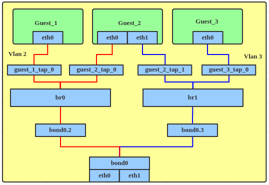
Figure 1: Traditional bridge-per-VLAN topology
In the case above, we have VLANs 2 and 3, which require br0 and br1 to be created on the host in order to allow those VLANs to be used by guests.
There are multiple disadvantages to using this topology:
- As the numbers of VLANs and guests on the host increases, the number of VLAN interfaces and bridges increases with them, adding complexity to the host's network configuration.
- If a guest needs access to more than one VLAN (like Guest_2 in the diagram above), it needs to have multiple NICs defined, each one connecting to a different bridge on the host.
- IPv6 must be disabled by default on the host, otherwise it will automatically acquire an address on every bridge interface. This is usually undesirable, since the guests might be public-facing but one might want to manage the host only from a local LAN or VPN connection.
According to the aforementioned blog post, bridge VLAN filtering has been available since Linux kernel 3.8 (released February 2013), but until I started researching new host networking topologies, I had not seen it in active use. So far it has been very stable for me, but I haven't looked into the code to see what sort of bugs might be present there or what sort of security history it has.
Advantages of VLAN filtering
VLAN filtering brings to Linux bridges the capabilities of a VLAN-aware network switch: each port on the bridge may be assigned to one or more VLANs, and traffic will only be allowed to flow between ports configured with the same VLANs. The VLANs may be tagged or untagged, and packets will have their VLAN id headers stripped or added as appropriate when they enter or leave the bridge.
The Red Hat blog post shows how the same guest topology shown above would look using VLAN filtering:
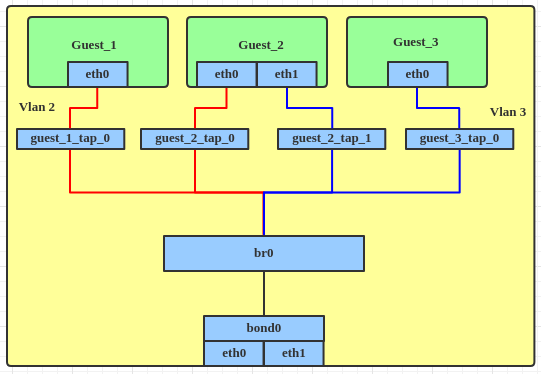
Figure 2: VLAN filter topology
Hopefully the advantages of this topology are apparent:
- It requires a single bridge and no VLAN interfaces on the host, so there's no configuration bloat. Guests may be added to multiple VLANs without requiring multiple host bridges.
- The host's addressing can be added under the untagged VLAN on the bridge interface independently of the guests, so there's no risk in having IPv6 enabled by default.
- One further simplification not mentioned in the Red Hat blog post is that guests may be connected to multiple VLANs without requiring additional NICs. Multiple NICs may be used if necessary - for performance reasons, for example - but they aren't required to take advantage of VLAN filtering.
A worked example
Here's an example scenario: we want to configure a host with a single NIC to act as:
- a web server,
- a firewall/router for wireless guests and the web server, and
- virtual desktops for selected guests
The host is connected to a managed switch which connects to a wireless access point and an Internet uplink. We want to manage both the wireless AP and the host on a separate management network which can't be accessed from the Internet or the web server.
Let's assign the following VLANs:
| VLAN id | Description |
| 10 | Management network |
| 20 | Web server - this might have been traditionally called a DMZ |
| 30 | Wireless guests |
| 40 | Virtual desktops |
| 50 | Internet |
Physically, the network might look like this:

(diagram courtesy of https://draw.io/)
And here's what the host network topology would look like:

(diagram courtesy of https://draw.io/)
Implementation details
To implement bridge VLAN filtering in TLNTC, I created a custom Ansible role. It involves the following components:
- A script which runs through networkd-dispatcher when the host NIC and bridge devices start. This script's role is to assign the correct VLANs on the NIC and the bridge.
- Another script which runs as a qemu hook when the guest starts. Its role is to assign the correct VLANs to the newly-created guest VM's virtual Ethernet device.
- An Ansible host configuration which is translated to JSON and saved as /etc/vlan-filters.json on the host. It defines which VLANs are assigned to which host devices and guests.
- Dependencies of the scripts, namely:
- bsdutils, to log the script output to syslog
- jq, to parse /etc/vlan-filters.json
- libxml-xpath-perl, to parse the qemu guest definition passed to the hook, and
- networkd-dispatcher, to invoke the host network scripts when the interfaces are configured. (One gotcha I encountered along the way was the need to use networkd-dispatcher's configured.d rather than configuring.d or routable.d for the host NIC - see the answer I added at Ask Ubuntu for details.)
The host configuration in Ansible (not included in the role, because it's site-specific) would look like this:
vlan_filters:
  guests:
    desktop1:
      untagged: 40
    desktop2:
      untagged: 40
    firewall:
      tagged: [10, 20, 30, 40, 50]
    web:
      untagged: 20
  interfaces:
    br0:
      filtering: true
      tagged: [20, 30, 40, 50]
      untagged: 10
    eth0:
      tagged: [10, 30, 50]
and when the role is executed, it will produce the following /etc/vlan-filters.json (compressed a little for brevity):
{
    "guests": {
        "desktop1": {
            "untagged": 40
        },
        "desktop2": {
            "untagged": 40
        },
        "firewall": {
            "tagged": [ 10, 20, 30, 40, 50 ]
        },
        "web": {
            "untagged": 20
        }
    },
    "interfaces": {
        "br0": {
            "filtering": true,
            "tagged": [ 20, 30, 40, 50 ],
            "untagged": 10
        },
        "eth0": {
            "tagged": [ 10, 30, 50 ]
        }
    }
}
A couple of notes about the configuration:
- VLANs 20 and 40 don't need to be present on the physical NIC or on the switch configuration. Because all traffic from the wireless guests and from the Internet must route via the firewall VM, these two VLANs need only to be configured on the host bridge and the guest VMs which use them.
- Assuming that the firewall provides DHCPv6 and router advertisements, the VMs desktop1, desktop2, and web don't need anything special configured - just by naming them with their correct names in the libvirt guest configuration, they will be assigned to the correct VLANs, and the usual DHCPv6 and SLAAC processes should get the correct addressing from the firewall.
- Even though I've heavily referenced the Red Hat developer blog for the background to this post, this Ansible role and the rest of the automation in my network assumes the use of Ubuntu or another Debian-based distribution.
Assuming we are using 2001:db8:1::/48 as our site network, the host network configuration using netplan might look like this:
network:
  ethernets:
    eth0:
      dhcp4: false
  bridges:
    br0:
      addresses:
      - 2001:db8:1:a::2/64
      interfaces:
      - eth0
      dhcp4: false
And the firewall's network configuration might look like this:
network:
  ethernets:
    eth0:
      dhcp4: false
  vlans:
    vlan10:
      addresses:
      - 2001:db8:1:a::1/64
      dhcp4: false
      id: 10
      link: eth0
    vlan20:
      addresses:
      - 2001:db8:1:14::1/64
      dhcp4: false
      id: 20
      link: eth0
    vlan30:
      addresses:
      - 2001:db8:1:1e::1/64
      dhcp4: false
      id: 30
      link: eth0
    vlan40:
      addresses:
      - 2001:db8:1:28::1/64
      dhcp4: false
      id: 40
      link: eth0
    vlan50:
      addresses:
      - 2001:db8:1:32::1/64
      dhcp4: false
      id: 50
      ipv6-privacy: true
      link: eth0
We'll side-step the subnet addresses I've chosen here for now (they're just the hexadecimal equivalents of the decimal VLAN ids)- this is just to give a general idea of the topology. In this example we're working with IPv6 only for simplicity, but bridge VLAN filtering works at layer 2, so it's independent of the IP version in use, and works equally well in a dual-stack or IPv4-only network.
Wrapping up
I've gone well over my intended word count on this tech nibble, but hopefully it has explained clearly how and why one would use bridge VLAN filtering over traditional bridging on a Linux VM host. If you think I've missed something, I've made any errors, or this explanation could be improved, please feel free to get in touch.